If the USB ports on a GFCI-USB combo receptacle USB still powered after GFCI trips, the device may be working as designed. The key question is whether the USB charging module is fed from the line side or the load side of the GFCI. For buyers, distributors, facility managers, and contractors, that internal architecture affects field expectations, return risk, inspection questions, and the exact question that should be asked before placing a purchase order.
The Short Answer for Buyers Comparing Combo Outlets
If you have installed a GFCI-USB combo receptacle and noticed that the USB ports keep delivering power after the GFCI trips, the device may be operating exactly as specified. On a line-side architecture SKU, the USB charging module is fed upstream of the GFCI relay, so a ground-fault trip de-energizes the 125V receptacle contacts while the low-voltage USB output remains active. On a load-side architecture SKU, the USB module is fed downstream of the GFCI relay, so pressing TEST shuts off both the AC receptacle and the USB ports.
Neither architecture is automatically wrong. The problem starts when the architecture does not match the room, the sales channel, or the user’s expectation. A facility buyer may accept line-side USB behavior for a dry office workstation. A retail customer testing a bathroom or kitchen combo device may expect every output on the face to go dead when the TEST button is pressed.
A complete combo product typically involves several evaluation areas: the receptacle portion, the GFCI function, and the integral Class 2 power supply that produces the USB output. Buyers should verify the listing, wiring diagram, and construction details for the specific SKU instead of assuming that every model in a family behaves the same way. The question to ask is simple: Is the USB charging module fed from the line side or the load side of the GFCI?
Why the USB Can Stay Powered After the GFCI Trips
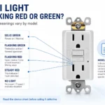
A GFCI receptacle monitors current imbalance and trips when the fault current reaches the personnel-protection range. UL material on ground-fault protective devices describes a Class A GFCI as tripping when the current to ground is in the 4 mA to 6 mA range and references UL 943 as the standard for ground-fault circuit interrupters. That trip action protects the receptacle path, but it does not automatically tell you where every internal low-voltage circuit inside a combo device is fed.
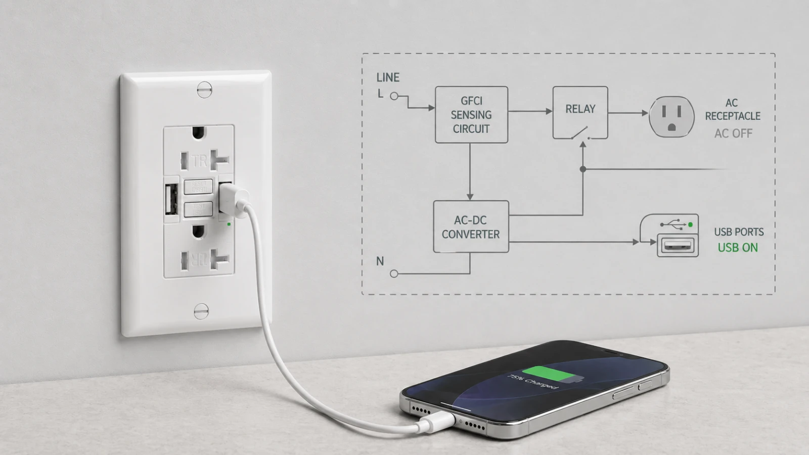
In a line-side architecture, the integral USB charging module draws its 120V AC input from the same side as the incoming line terminals. When the GFCI relay opens the protected receptacle path, the AC feed to the USB DC converter may still be energized. The receptacle face can therefore show a tripped GFCI while the USB ports continue delivering 5V charging output until the upstream breaker, switch, or branch-circuit feed is turned off.
In a load-side architecture, the USB converter is fed after the GFCI trip mechanism. When TEST is pressed or a ground fault trips the device, the AC receptacle and the USB converter lose power together. This behavior is easier for homeowners, tenants, and maintenance staff to understand because “tripped” visually means that every usable output on the device face is off.
Simplified internal architecture comparison
Line-side USB architecture

Incoming LINE
   ├─ GFCI sensing / relay → 125V receptacle contacts + downstream LOAD
   └─ AC-DC converter → USB ports

After TEST or trip:
125V receptacle = OFF
Downstream protected load = OFF
USB ports = may remain ON
Load-side USB architecture

Incoming LINE
   └─ GFCI sensing / relay → 125V receptacle contacts + downstream LOAD + AC-DC converter → USB ports

After TEST or trip:
125V receptacle = OFF
Downstream protected load = OFF
USB ports = OFF
This is why a “USB still powered” complaint cannot be judged from the face of the device alone. The buyer has to know the internal feed point.
Why Line-Side USB Architecture Exists
Line-side USB architecture is not necessarily a shortcut. It can be a deliberate engineering choice.
The USB charger inside a combo outlet is a switching power supply. It converts 120V AC into low-voltage DC output for phones, tablets, and small electronics. Switching converters create high-frequency noise that engineers have to manage through layout, filtering, shielding, spacing, and routing. If the USB power stage is placed close to the GFCI sensing path, electromagnetic noise and filtering become design concerns that must be controlled carefully.
Feeding the USB module from the line side can simplify that interaction. It can keep the switching power stage out of the protected load path and reduce the chance that noise from the USB converter influences the GFCI sensing circuit. It can also simplify the internal layout in a device that already has limited space for the GFCI electronics, relay, terminals, USB converter, heat management, and face structure.
From a manufacturing perspective, this is the part that catalog pages rarely explain. The product face may look like a simple combination outlet, but the internal layout is crowded. A small change in USB feed location can affect PCB routing, filter design, thermal rise, test procedure, and field behavior after a trip. This is why buyers should not treat “GFCI with USB” as one universal architecture.
Why Load-Side USB Architecture Exists
Load-side USB architecture gives the user a cleaner mental model: when the GFCI trips, everything on the face stops delivering usable power. That matters most in kitchens, bathrooms, outdoor boxes, commercial restrooms, laundry areas, and other locations where GFCI protection is strongly associated with wet or damp conditions.
Recent NEC cycles have expanded GFCI coverage in several dwelling and non-dwelling locations. Eaton’s NEC 2023 material notes that Sections 210.8(A) and 210.8(B) expanded GFCI protection to all receptacles found in the kitchen. In that environment, many users do not think in terms of internal tap points. They press TEST and expect the device face to go dead.
For retail channels, load-side behavior can reduce confusion. A homeowner may not distinguish between a 125V receptacle and a 5V Class 2 USB output. If the phone keeps charging after TEST is pressed, the product may be returned as defective even if the GFCI function worked correctly. For contractors and property managers, that misunderstanding becomes a support call or a callback.
This is the practical reason many buyers prefer load-side behavior for SKUs intended for kitchens, bathrooms, outdoor receptacle boxes, hospitality bathrooms, rental units, and DIY retail shelves. It is less about saying the architecture is legally required in every case, and more about reducing ambiguity in the room where the device will be used.
Line-Side or Load-Side: Which Architecture Fits Your Project?
The choice between line-side and load-side architecture is not a quality ranking. It is a fit decision.
Line-side USB architecture may fit dry convenience-charging locations
Line-side USB behavior can be appropriate in dry locations where the USB charging function is the main value and the user is not relying on the TEST button as a whole-face shutoff signal. Examples include office workstations, hotel guest-room desks, bedside locations, conference rooms, corridors, and similar convenience-charging points where the installation context does not create a wet-location expectation.
In those applications, the buyer may care more about stable USB charging, fewer nuisance interactions, and predictable low-voltage output than about having the USB ports shut off together with the receptacle contacts. The architecture still needs to match the product listing, installation instructions, and local code requirements, but the user expectation is different from a bathroom or kitchen.
Load-side USB architecture may fit wet, damp, retail, and high-scrutiny locations
Load-side USB behavior is usually the lower-risk procurement choice for kitchens, bathrooms, outdoor receptacle boxes, commercial restrooms, laundry areas, and hospitality bathrooms. In those rooms, the user expects the GFCI TEST button to make the entire device face visibly inactive. Inspectors, maintenance staff, and homeowners may also evaluate the device through that same expectation.
For a distributor stocking one SKU across both contractor and DIY channels, load-side behavior is often easier to support. The return desk does not need to explain internal USB feed architecture. The contractor does not need to defend a partial-live face during a project review. The product behaves the way non-specialists expect it to behave.
What Goes Wrong When the Architecture Lands in the Wrong Channel
This is the pattern procurement teams remember.
A distributor stocks a GFCI-USB combo receptacle with line-side USB architecture. The catalog photo looks clean. The face is modern-style. The product has a 15A or 20A NEMA configuration, tamper-resistant AC receptacle slots, self-test GFCI function, and built-in USB charging. The spec sheet looks complete enough for a purchasing department.
The unit then ships into a retail channel. A homeowner installs it in a kitchen or bathroom, plugs in a phone, and presses the TEST button. The AC receptacle goes dead. The phone keeps charging. The homeowner concludes the TEST button failed because the device face still appears to provide power. The product is returned, even though the line-side USB behavior may have matched the internal design.
At the factory level, that same behavior may have been part of the test plan. If the work order specified line-side USB, the technician may trip the GFCI and confirm that the USB output remains stable at 5V. In that case, the returned unit is not failing the factory specification. It is failing the channel expectation.
This is why the line-side vs load-side decision belongs in the RFQ stage. It is not enough to ask for “a GFCI with USB.” The supplier needs to identify the USB feed point, and the buyer needs to decide whether that behavior fits the room and the customer.
What an AHJ or Project Reviewer May Question
During some damp-location project reviews, inspectors or contractors may press the TEST button and observe what de-energizes. If the AC receptacle turns off but the USB output remains active, the reviewer may ask whether the installed product matches the expected GFCI behavior for that location.
The NEC does not appear to name the line-side vs load-side USB tap point directly. NEC 210.8 addresses locations requiring GFCI protection for receptacles. The NEC has addressed receptacles with integral USB chargers by requiring a 125V 15A or 20A receptacle that additionally provides Class 2 power to be listed and constructed so the Class 2 circuitry is integral with the receptacle. In the 2017 NEC, this language appeared as 406.3(F), Receptacle with USB Charger. Buyers should verify the exact section number against the NEC edition adopted by the local jurisdiction. That is not the same as saying the code explicitly tells the manufacturer where the USB converter must be fed inside a GFCI combo device.
The AHJ may still have the final say on the jobsite. A project reviewer may not frame the concern as a line-by-line code debate. The practical concern is that the GFCI label and TEST button can imply whole-device protection to a homeowner, tenant, or maintenance person. In a damp or wet location, that perception matters because the device is being judged by how safely and clearly it communicates its state.
For that reason, a buyer specifying for NEC 210.8 locations should usually treat load-side USB behavior as the lower-risk path unless the product documentation, project design, and AHJ expectation clearly support another approach. Code section numbers and requirements should always be verified against the NEC edition adopted by the local jurisdiction.
The One Question to Ask Before Placing the PO
If a buyer remembers only one line from this article, it should be this:
On this SKU, is the USB charging module fed from the line side or the load side of the GFCI?
The answer should be direct and should match the wiring diagram, internal construction, product instructions, and inspection test plan. If the supplier answers only with “the device is fully listed” but cannot explain the USB feed point, treat that as a documentation gap before ordering.
For GFCI-USB combo projects, the buyer should also ask:
- Trip-state behavior: When the TEST button is pressed, do the USB ports remain powered or shut off?
- Internal tap point: Is the USB AC input fed before or after the GFCI relay?
- Documentation: Does the wiring diagram show the USB feed point clearly?
- Application fit: Is the SKU intended for dry convenience charging, damp-location GFCI use, retail channels, or contractor-specified projects?
- Inspection expectation: Will the local AHJ or project reviewer expect all face outputs to de-energize during TEST?
- Replacement risk: If the user complains that USB stays powered after trip, will the support team classify that as normal behavior or a defect?
That checklist is more useful than comparing only color, amperage, USB port count, or face style. The line-side/load-side question is one node in a longer GFCI sourcing decision — where protection sits, which device that implies, what to document — set out in where the USB feed choice fits the wider GFCI decision.
How to Verify the Behavior During Sampling
Buyers do not need a full lab to identify the trip-state behavior of a sample. They need a controlled test and clear documentation.
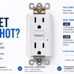
- 1. Confirm correct wiring first. Identify LINE and LOAD according to the product instructions. Do not use a trip-state test to compensate for uncertain wiring.
- 2. Energize the sample safely. Use a qualified technician and a controlled test setup. Verify the AC receptacle is powered.
- 3. Confirm USB output. Plug in a small USB load or meter and confirm the ports are delivering output.
- 4. Press TEST. Confirm that the GFCI trips and that the AC receptacle contacts de-energize.
- 5. Observe the USB output. Record whether the USB remains active or turns off after the trip.
- 6. Match the result to the spec. If the SKU was sold as load-side behavior but the USB remains active, the sample may not match the requested construction.
From an incoming inspection perspective, this is a valuable check. Buyers often inspect packaging, color, markings, terminal screws, reset feel, and face appearance, but they do not always record what happens to the USB output after the GFCI trips. For GFCI-USB combo devices, that behavior should be part of the sample approval record.
Where This Fits in USB-C and GFCI Product Selection
This architecture question becomes more important as USB charging moves from low-output phone charging into higher-power commercial and hospitality applications. In a hotel, office renovation, apartment upgrade, or student housing project, the buyer may be comparing standard receptacles, GFCI receptacles, USB-A charging, USB-C charging, and higher-output PD devices at the same time.
For broader context on how USB-C charging is being specified into hotel, office, and renovation projects, see our earlier article on 65W dual USB-C wall outlet adoption in commercial environments. That article explains the demand side of high-power USB charging. This article explains the trip-state behavior question that comes up when USB charging is integrated into a GFCI device.
For SKU-level review of a current combo model, see our 15A USB GFCI receptacle with dual USB-A ports. For projects that decide to keep USB out of damp-location GFCI points and use a standard protective device instead, review the broader GFCI receptacle range before the device schedule is finalized.
Frequently Asked Questions About USB Ports Staying Powered After a GFCI Trip
Is a GFCI broken if the USB ports still have power after it trips?
Not always. The device may be working as designed if the USB charging module is fed from the line side of the GFCI. In that architecture, the 125V receptacle contacts can open during a trip while the 5V USB output remains active. A wiring error, damaged device, or wrong SKU should still be ruled out by checking the product instructions, wiring diagram, and documented trip-state behavior.
Does NEC require the USB outputs in a combo outlet to shut off when the GFCI trips?
NEC 210.8 specifies locations where receptacles require GFCI protection. Separate NEC language has addressed receptacles with integral USB chargers by requiring the Class 2 circuitry to be integral with the receptacle; in the 2017 NEC, that USB charger language appeared as 406.3(F). The exact section number should be verified against the NEC edition adopted locally. The code language does not directly name the internal line-side or load-side tap point for the USB module. Field acceptance may still depend on the AHJ, the product listing, the installation instructions, and the expected behavior in that room.
What is the difference between line-side and load-side USB architecture?
Line-side USB architecture feeds the USB charging module before the GFCI relay, so the USB ports may stay powered after the GFCI trips. Load-side USB architecture feeds the USB charging module after the GFCI relay, so the USB ports shut off with the AC receptacle when the device trips. The right choice depends on the application, support expectation, and inspection context.
Is line-side USB architecture safe?
Line-side USB architecture can be appropriate when the product is listed, installed according to instructions, and used in a location where that behavior matches the project expectation. The question is not whether the architecture is automatically safe or unsafe. The question is whether the SKU fits the room, the local code context, the AHJ expectation, and the end user’s understanding of the TEST button.
Can I tell from a spec sheet whether a USB GFCI outlet is line-side or load-side?
Sometimes, but not reliably. A good spec sheet or submittal should state the trip-state behavior or include a wiring diagram that shows where the USB module receives its AC input. If the document does not say, ask the supplier directly: “On this SKU, is the USB charging module fed from the line side or the load side of the GFCI?”
Should I specify load-side USB behavior for bathrooms and kitchens?
Load-side USB behavior is usually the lower-risk procurement choice for bathrooms, kitchens, outdoor boxes, laundry areas, commercial restrooms, and similar NEC 210.8 locations. It aligns with the common expectation that pressing TEST shuts off all usable outputs on the device face. Local code adoption, AHJ interpretation, and the product installation instructions should still be verified before final specification.
Before You Spec or Order
The fastest way to avoid confusion is to make USB trip-state behavior part of the purchasing conversation. Do not wait until a homeowner, tenant, electrician, or inspector discovers the behavior after installation.
- For dry convenience-charging locations: line-side USB behavior may be acceptable when the project expects the USB function to stay available and the location does not create a wet-condition GFCI expectation.
- For kitchens, bathrooms, outdoor boxes, and commercial restrooms: load-side behavior is usually the lower-risk path because it matches what most users expect from the TEST button.
- For retail channels: load-side behavior can reduce returns from buyers who interpret any live USB output after TEST as a defect.
- For contractor channels: the wiring diagram and submittal should clearly state the USB feed point so the installer knows what behavior to expect.
- For factory inspection: trip-state USB behavior should be written into the sample approval and IQC test plan.
Need help checking GFCI-USB architecture before the PO is released?
Send us the target room, required amperage, USB output requirement, and expected trip-state behavior. We can help review whether a GFCI-USB combo receptacle or a standard GFCI receptacle is the cleaner fit for the project.
Related articles on this site
- Why 65W Dual USB-C Wall Outlets Are Gaining Ground in Hotels, Offices, and Modern Renovation Projects
- 2026 NEC Code Changes: Critical Updates for GFCI and Receptacle Installations
- TR and WR Receptacle Selection Guide: The Ultimate NEC Compliance FAQ
- HVAC GFCI Nuisance Tripping in 2026: HF GFCIs, Class C SPGFCIs, and the NEC 210.8(F) Deadline
Related product links
Sources and references
- UL Code Authorities: Understanding Ground Fault and Leakage Current Protection
- Leviton: Installing and Testing a GFCI-USB Charging Receptacle
- Eaton: GFCI 210.8(A) Dwelling Units — NEC 2023
- Eaton: Electrical Safety NEC 2023 Updates
- ElectricalLicenseRenewal.com: 2017 NEC 406.3(F) Receptacle with USB Charger
- Reddit r/AskElectricians: User question about USB ports staying live after a GFCI trip
- SYGFCI: 15A Combination USB GFCI Receptacle with Dual USB-A
- SYGFCI: GFCI Outlets Category