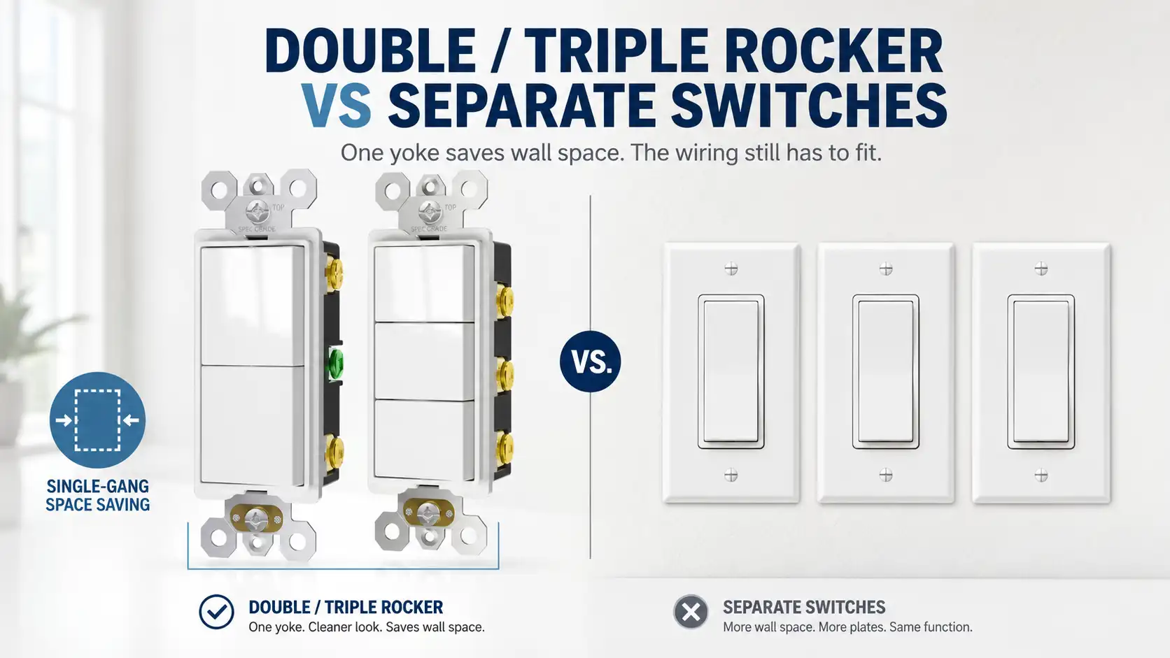
Put three single-pole switches on one yoke and the device fill drops from twelve cubic inches to four. In the worked example below, the box you just moved them into holds thirty-six cubic inches less. Nothing in the wall changed — same conductors, same splices, same grounds, now in one-third of the listed box volume that example started with.
Our UL- and cUL-listed wiring-device lines include GFCIs, USB outlets, receptacles and switches. We also produce matching wallplates and slab boxes. We sell to distributors and contractors in North America. What we lock before a shipment leaves is the device side. Pole isolation, terminal count, the marked rating, body depth, the opening our faces fit. Whether the box behind the plate has room, and whether the wall already carries the conductors the device needs, gets settled on site. Those two turn out to decide more than the switch on the PO does.
Two rockers do not make two switched hots
The question underneath most of this: a bathroom has one switch running a fan and a light together, and someone wants them separate. Swap in a double rocker, get two buttons, problem solved.
That’s the part that doesn’t hold up. A rocker is a switching mechanism. It opens and closes one path. Putting two of them on one body gives you two mechanisms, and nothing else. If the fan and the light both hang off a single switched hot in the ceiling box, that conductor stays single. It doesn’t care what device sits at the wall. Both loads still go on and off together, now with a spare button that does nothing.
What has to already exist in the box, before the device matters at all:
- a line hot feeding the location
- one separate switched conductor per load, running to that load
- a neutral arrangement the loads and the location need
- an equipment ground
- volume left over for all of it
Count the actual conductors and identify where each one goes. The cable count alone does not establish how many independently switched loads are available. A cable can be a feed-through, a switch loop, a load connection, or part of a multiwire arrangement. It can be more than one of those at once. The face of the device tells you nothing about any of it.
Two buttons are a device choice. Two switched conductors are a wiring condition, settled when the house was wired.
The neutral rides along with that count. NEC 404.2(C) requires a grounded conductor at covered lighting-switch locations, subject to the exceptions in that section. Many timers, occupancy sensors and illuminated controls need a neutral at the switch location, and the device wiring diagram decides it. A location wired before that requirement took hold has the hots and no white. That narrows the upgrades available later, before any device is chosen.
Where the loads already have separate legs, a combination device works exactly as advertised. An old two-gang location being consolidated, say. Or a rough-in done with the split in mind. That is the new-construction case. The question arrives from the other direction — a retrofit, someone working hard not to open the wall.
We do not pack an installation sheet with these ordinary switches. We mark the device and the terminal layout. The field wiring method stays with the installer and the adopted code.
What the 15A on the face actually covers
Our double and triple rockers are marked 15A, 120/277V, and they carry no horsepower rating.
The first mistake is arithmetic. Three rockers marked 15A is not a 45A device. On some products the marking states a per-pole rating. On others it states the rating for the device as a whole. That difference comes from how the product was listed. Read the part in front of you. Don’t extrapolate across a catalog.
The second mistake is load type, and the code is specific about it. An AC general-use snap switch is permitted to control resistive and inductive loads up to the ampere rating at the voltage applied. Tungsten-filament lamp loads up to the ampere rating at 120 volts. Motor loads up to 80 percent of the ampere rating at rated voltage. Later editions add electric-discharge lamp loads at the marked rating. They also cover electronic ballast, compact fluorescent and LED driver loads, capped at 20 amperes and at the switch rating.
That 80 percent line is the one that matters in a bathroom. A 15A switch tops out at a 12A motor load. An exhaust fan is a motor load. So is the fan half of a fan-light-heater assembly. When the heater nameplate, the branch-circuit requirement or the appliance instructions call for a separate circuit, that load needs its own control path.
A resistive heater in the same assembly answers to a different line in the same rule. Resistive loads run to the full ampere rating, not to 80 percent. One switch, two ceilings, depending on what is hanging off each rocker.
Without a horsepower marking, 80 percent is the ceiling on the motor, and no amount of reading the face differently moves it.
Two more markings decide what can land on the terminals, and both belong on a spec line rather than in a surprise at rough-in. Terminals on 15A and 20A snap switches not marked CO/ALR are for copper and copper-clad aluminum only. Direct connection to aluminum branch conductors calls for the CO/ALR marking. Screwless push-in terminals carry their own limit. The code holds them to branch circuits of 15 amperes or less, wired with 14 AWG solid copper. A product listed and marked otherwise is the exception. On a 1960s retrofit with aluminum branch wiring, that first marking decides whether the box gets pigtailed or the device gets rejected.
Isolated terminals are a construction, not a permission
Our double and triple rockers have fully isolated poles. Each pole has its own line terminal — two terminals per pole, no shunt bar tying the line side together across the device.
That looks like permission to feed each rocker from a different branch circuit. It is not, and this is the part worth reading twice before an order goes out.
A multipole general-use snap switch is not permitted to be fed from more than a single circuit unless it is listed and marked as a two-circuit or three-circuit switch. The rule arrived in the 2008 cycle with a second path attached: a switch whose voltage rating covered the line-to-line voltage of the system. The 2011 NEC still allowed it. The 2014 NEC removed it. What remains is the marking.
The certification side says it in its own words. Guide information for snap switches puts it plainly. Multi-pole general-use snap switches have not been investigated for operation on more than a single circuit, unless marked “2-circuit” or “3-circuit.”
We do not carry that marking. So on our devices: one circuit, isolated poles or not. The isolation buys clean separation of the switch legs downstream, and nothing upstream of the line terminals.
Two more rules sit behind that one, and they survive even where a properly marked device exists. Where two or more branch circuits supply devices on the same yoke, the ungrounded conductors have to disconnect simultaneously. That happens at the point the circuits originate. Handle ties identified for the purpose, or a common-trip breaker. And a snap switch cannot be grouped with other devices where the voltage between them exceeds 300 volts, unless barriers are installed between them.
We can develop a break-off-tab version as a separate certified construction. It cannot carry a two-circuit or three-circuit claim until that construction and its marking are covered by the certification file. What we can’t hand a buyer is a marking we don’t hold.
The one cut the yoke makes
The code counts devices by yoke, not by button. For each yoke or strap containing one or more devices, a single double-volume allowance is made, based on the largest conductor connected to that yoke.
One or more. Three rockers on one strap draw one allowance. Three switches on three straps draw three. That saving is real, and it is the entire mechanical argument for a combination device.
Here it is with numbers. One location, three independently switched loads — exhaust fan, vanity light, mirror light. 14 AWG throughout, one supply cable in and three cables out. Internal cable clamps present, four grounds.
| Box-fill item | Triple rocker, one gang | Three switches, three gangs |
|---|---|---|
| 8 insulated conductors @ 2.0 in³ | 16.0 | 16.0 |
| Grounds (four counted as one) | 2.0 | 2.0 |
| Internal cable clamps | 2.0 | 2.0 |
| Device yokes | 1 yoke → 4.0 | 3 yokes → 12.0 |
| Volume required | 24.0 in³ | 32.0 in³ |
| Box volume available | 18.0 in³ | 54.0 in³ |
| Result | over by 6.0 | 22.0 to spare |
Example only. Use the listed volume of the actual box and the conductor sizes present on the project.
The ground line sits on a boundary worth knowing. Four grounds count as one allowance together. The fifth adds a quarter, and so does every one after it. Four cables in and out puts the location right at that edge.
The single-gang install fails, and it fails on the cheap side of the ledger. Drop the clamps and it still needs 22 against 18. Move to a deep single-gang plastic box at 22.5 and it still comes up short. The eight cubic inches saved on device-yoke fill never covered the thirty-six lost when this example moved from three gangs to one.
The wider arrangement asks for more device fill and passes anyway, because it brought its own volume along.
One more thing this arithmetic ignores. Box fill counts conductors, not the physical size of what you screw to the yoke. Our bodies run 1.23 inches deep, which is shallow, and that number does nothing for the calculation above. A slim device and a compliant box are separate questions.
One gang, one opening
Rocker count is not gang count. A single, a double and a triple all mount in one single-gang position and sit behind the same standard decorator opening. Three rockers do not call for a three-gang plate.
Our wallplates use that opening across the range, and plates are ordered separately from devices.
The opening is settled, then. Depth and fill are still open, and they are what the location gets judged on. How a particular inspector reads a box-fill calculation that lands within a cubic inch of the limit, I can’t tell you in advance.
FAQ
Can I replace two single switches with one double rocker switch?
Only if the box already contains a separate switched conductor for each load. The device supplies mechanisms, not conductors.
Does a double or triple rocker fit a standard single-gang box?
It fits a single-gang opening. Whether it fits the box depends on the box fill calculation for that location, which counts conductors rather than the device.
Does a combination switch reduce box fill?
It reduces the device portion — one yoke instead of two or three. Everything else stays, and moving from a three-gang box to a single-gang box removes far more volume than the yoke saving returns.
Is a 15A rating per rocker or for the whole switch?
Do not multiply the face rating by the rocker count. Use the per-pole and total-device ratings stated for that exact model.
Can each rocker be fed from a different circuit?
Not unless the switch is listed and marked as a two-circuit or three-circuit switch. Isolated terminals on their own do not authorize it, and ours are not so marked.
When separate switches are worth the wall
If the wall can’t be opened and the loads already have their own legs, the combination device does the job it was built for.
Separate switches win when the project needs different control types, different ratings or individual replacement. A timer on the fan. A dimmer on the light. A 20A path for the heater. One function replaced without disturbing the other two. Each of those wants its own yoke. The combination switch buys wall width. It pays in volume, in circuit choices, and in the day one rocker fails and the whole device comes out.
Sources and Internal Basis
Primary Code and Certification Sources
- NFPA 70, National Electrical Code, 2023 edition. Primary code basis for 404.2(C), 404.8(B), 404.8(C), 404.14(A), 404.14(D), 210.7, 314.16(A), Table 314.16(A), Table 314.16(B), 314.16(B)(2), 314.16(B)(4), and 314.16(B)(5).
NFPA 70 official standard page - UL Product iQ — General-Use Snap Switches, CCN WJQR. Certification guide information for snap-switch scope, product markings and the limitation on multi-pole switches used on more than one circuit unless marked “2-circuit” or “3-circuit.” Search the category code WJQR in Product iQ.
UL Product iQ - UL 20, General-Use Snap Switches. Product-standard basis for permanently connected general-use snap switches and modular switch assemblies used with branch-circuit wiring.
UL Standards Catalog
Section-Level Technical References
- IAEI Magazine, “Code Hunter — Support, 2014 NEC.” Used for the 314.16(B)(4) rule that one yoke or strap containing one or more devices receives a double-volume allowance; the worked example identifies 4.0 in³ for a yoke connected with 14 AWG conductors.
IAEI device-yoke fill reference - IAEI Magazine, “Analysis of Changes — 2020 NEC (Part I).” Used for the revised 314.16(B)(5) equipment-grounding-conductor calculation: one full allowance through four EGCs, then an additional one-quarter allowance for each EGC beyond four.
IAEI equipment-grounding-conductor fill update - Electrical Contractor Magazine, “Box-Fill Calculations, Part VII.” Used for the distinction between conductor fill and device-yoke fill, including single, double and triple switches installed on one yoke.
Electrical Contractor device-fill explanation - EC&M, “NEC Requirements for Switches.” Used for 404.14 rating and use of AC general-use snap switches, including the 80-percent motor-load limit.
EC&M switch-rating reference - IAEI Magazine, “Residential Lighting under the NEC.” Used for the 2023 application of 404.2(C), including grounded-conductor availability at covered lighting-switch locations and the section’s exceptions.
IAEI 2023 switch-location reference - Leviton Captain Code 2023, 404.14(D). Used for the exact 2023 snap-switch termination rules: unmarked 15A and 20A terminals for copper and copper-clad aluminum, CO/ALR terminals for aluminum as well, and push-in terminals limited to 15A circuits with 14 AWG solid copper unless otherwise listed and marked.
Leviton 404.14(D) termination summary - EC&M, “Code Q&A” (May 2008). Used to document the 2008-era 404.8(C) alternative that allowed multi-circuit use where the switch voltage rating was not less than the nominal line-to-line voltage.
EC&M 2008 multipole-switch reference - Leviton Captain Code, 404.8(C). Used for the later code-cycle change: the voltage-rating alternative remained in the 2011 NEC and was removed in the 2014 NEC, leaving the two-circuit or three-circuit listing and marking route.
Leviton 404.8(C) change summary
Internal Basis
- ShengYu double- and triple-rocker construction: fully isolated poles, separate line and load terminals for each pole, and no internal line-side shunt across the device.
- ShengYu product markings and certification scope: 15A, 120/277V; no horsepower marking; no “2-circuit” or “3-circuit” marking on the models discussed.
- ShengYu mechanical dimensions: 1.23-inch device-body depth and one standard single-gang decorator opening for the single-, double- and triple-rocker range.
- ShengYu product-scope boundary: a break-off-tab version would be treated as a separate certified construction and could not carry a multi-circuit claim until covered by the certification file and marking.
Double and triple rockers for standard single-gang openings
Double and triple rockers with isolated poles, standard decorator opening, marked 15A 120/277V. → ShengYu switches