In November 2024, a distributor in Florida forwarded me an email from his contractor on a residential renovation. The contractor had installed our 15A GFCI receptacles at the job site, and from his side, none of them worked out of the box. The reset button clicked but nothing latched. The faces stayed dark.
I asked him to send the installation video.
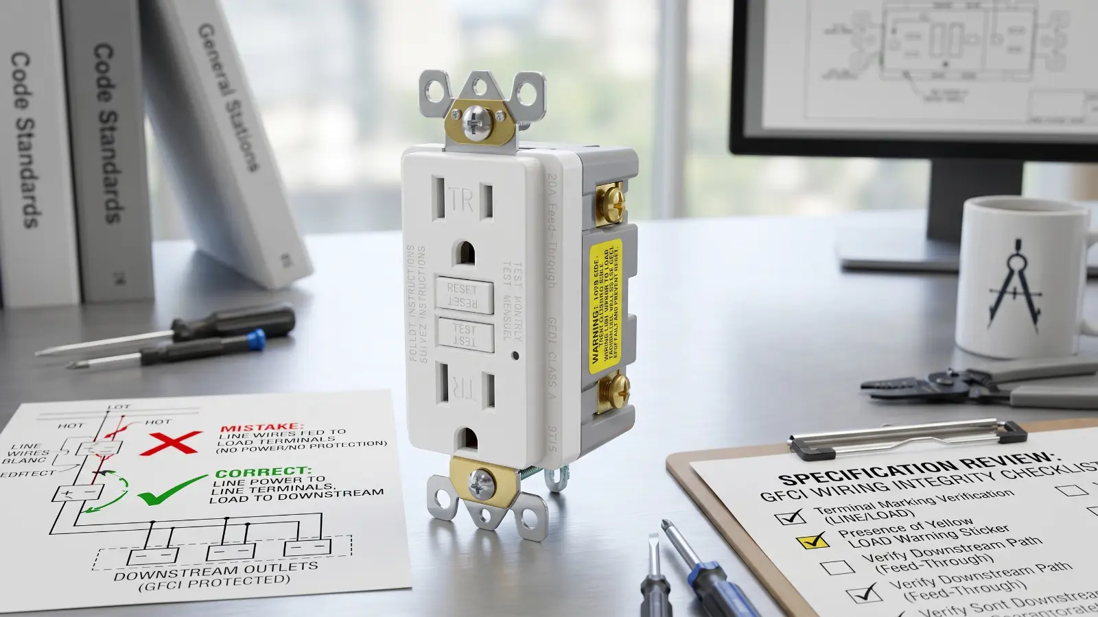
About thirty seconds in, the problem was visible at the device back: LINE and LOAD had been reversed. The lockout circuit on the GFCI was refusing to reset. The device was doing exactly what its lockout was designed for.
A basic LINE-side voltage check before connecting LOAD would have caught the issue quickly. On professional jobs, checking the LINE side before blaming the device is the safer habit. We do not sell into the individual DIY market, so install errors at that level are not really in our channel. When a “GFCI outlet won’t reset” complaint comes back to us, it usually comes through a distributor whose end customer is dealing with a wiring-side issue, a renovation box with unclear conductors, or a device generation change they did not expect.
GFCI line vs load: what happens when LINE and LOAD are reversed
There are two generations of GFCI on the market right now.
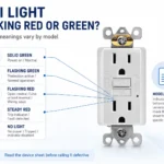
Older, non-self-test units made before later UL 943 reverse-miswire requirements could power up looking normal when LINE and LOAD were swapped. The face would light. TEST and RESET would cycle. Downstream outlets could have power but no intended protection — and nothing on the device would make the mistake obvious from the front.
Newer lockout-equipped models, including the 15A self-test units in the Florida case, behave differently. They refuse to reset when LINE and LOAD are reversed. Pushing RESET clicks, but nothing latches. The face stays dark. From the installer’s side, the device looks broken. The device is doing what its lockout circuit was designed to do.
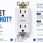
For GFCI outlet wiring, a device that will not reset on a new install usually points to one of three things: LINE/LOAD position at the device, no supply voltage at the LINE terminals, or a downstream fault connected to the LOAD side. The device itself should not be the first assumption.
For terminology background, “GFI” and “GFCI” refer to the same protection category in everyday North American use, even though GFCI is the better term for product specifications, UL references, and submittal documents.
What this looks like from our end
I have been on the sales side at ShengYu for fifteen years. The company itself is twenty years old. Across that span, formal return cases for “won’t reset” or “doesn’t work after install” have been rare in our channel.
In the returned cases we could verify, the units tested to spec on our QC line. The fault traced back to the install condition: LINE and LOAD reversed, a downstream issue connected to LOAD, or a wiring path the installer had not isolated yet.
What I can speak to is the production side. Each GFCI receptacle goes through full-function testing before shipment. That does not mean a device-side defect is impossible. It means a newly installed GFCI that will not reset deserves a wiring check before another replacement is ordered. Pls have a look at our test machine, we always do 100% test before we ship them out- Inside ShengYu’s UL/cUL Wiring Device Production Line.
The yellow sticker on every unit
Every GFCI we ship has a yellow warning sticker covering the LOAD terminals. I do not know the exact year our line first added it; it has been factory-default for as long as I have been at the company. It is industry-standard packaging for this exact category of mistake.
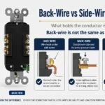
An installer who is not reading carefully can still peel it off and land the wires the same way they always have. The sticker does not prevent a wiring mistake by itself. What it does is force a half-second mechanical pause at the LOAD side, which is the side that traps less experienced installers.
The same packaging also includes the wiring diagram, the mounting screws, the “GFCI Protected” labels meant for downstream outlets, and the faceplate. None of this is unique to us. It is standard kit on a UL-listed GFCI receptacle from any serious manufacturer.
Downstream outlets can have power without GFCI protection
The other complaint type we see in distributor emails is about downstream outlets — specifically, receptacles that someone believed were GFCI-protected but later turned out not to be. This is still a wiring question, not a product question. From our side, the procurement point is whether the installer had the right device markings, wiring diagram, and downstream labels in the box.
A single GFCI receptacle at the first position on a circuit can protect downstream receptacles, but only when the downstream cable lands on the LOAD terminals, not on LINE. A GFCI protected outlet downstream has no reset button of its own, so visually it looks identical to a receptacle that has no protection at all. The way to map protection on an existing install is to press TEST on the upstream GFCI and confirm which downstream outlets lose power. Visual inspection alone does not prove protection.
This is where older or incorrectly wired installations become confusing. A downstream receptacle may continue to deliver power even though it is not actually protected by the upstream GFCI. That can happen when the downstream cable was landed on LINE instead of LOAD, or on older devices where a LINE/LOAD reversal did not produce a clear lockout symptom.
This is part of why we ship “GFCI Protected” labels in the box — so the installer can mark which downstream outlets are tied to which upstream device. Whether those labels get used is a different question.
Shared neutrals can make a good GFCI look bad
A second pattern that comes up in emails is the complaint that “the GFCI keeps tripping with nothing plugged in.” One wiring pattern worth checking is a shared neutral.
In some older homes and renovation layouts, two 120-volt circuits may share a single neutral conductor back to the panel. If that shared neutral gets carried through the LOAD side of a GFCI, or if downstream neutrals from more than one circuit are tied together after the device, the GFCI sees current returning that it never sent out. It trips because the wiring path creates an imbalance.
Kitchen and laundry layouts are common places for this to be questioned because more than one circuit may pass through the same box. We do not design branch circuits and we do not visit job sites, so the procurement-side observation is narrow: when a contractor reports that a GFCI keeps tripping with nothing plugged into the face, the wiring path is where we would start looking. Specifically: whether the circuit has a shared neutral, mixed downstream neutrals, or another downstream condition connected to the LOAD side.
That answer usually comes faster than replacing the device again. In some renovation work, electricians may evaluate a two-pole GFCI breaker at the panel or another upstream protection method, depending on the actual circuit and local inspection requirements. The important point for the buyer is simpler: a repeat trip does not automatically prove the GFCI device is bad.
One design point on GFCI with USB combos
There is one product-specific point worth mentioning because it creates its own version of the “GFCI doesn’t work” complaint.
On our GFCI receptacles with USB ports, the USB module is tapped from the LINE side of the device. That was a design choice for practicality and a simpler internal layout. The consequence is that USB ports can keep delivering power even after the GFCI trips and the AC outlets on the same face go dead.
If the user sees a phone still charging through the USB ports, they assume the whole device is working. It is not. The GFCI has tripped, and the AC outlets are off. The AC outlets are the correct signal of GFCI state on these combo units.
The fuller explanation is in our separate post on LINE-side vs LOAD-side combo design.
What to check first
When a newly installed GFCI does not reset, the wiring side deserves the first look.
Check the LINE and LOAD position at the device back. Confirm supply voltage at the LINE terminals. Check whether anything downstream on the LOAD side is shorted, miswired, or tied into a shared neutral path. If downstream outlets are supposed to be protected, press TEST on the upstream GFCI and confirm which receptacles actually lose power.
If the unit is one of ours and it tested clean at the factory, replacement of the device should come after those checks, not before them.
The packaging that ships with each receptacle — the wiring diagram, the “GFCI Protected” labels for downstream outlets, the yellow LOAD warning sticker, the screws, and the faceplate — exists for the same reason this article does: to narrow the gap between the install and the spec. Narrowing that gap between the install and the spec is the whole job of the GFCI receptacle sourcing map we wrote for project buyers, where the wiring check stays where it belongs — after the circuit, not as the first guess.
Our GFCI receptacle line is here for projects sourcing UL/cUL-listed devices.
Sources and References
Primary
- U.S. Consumer Product Safety Commission: GFCI Fact Sheet
- OSHA: Ground-Fault Circuit Interrupters
- UL Solutions: GFCI Personal Protection Devices Testing and Certification
- IAEI UL Question Corner: Self-Testing GFCI Requirements
- UL Code Authorities: GFCI Reverse Line-Load Miswire Requirements
Supporting