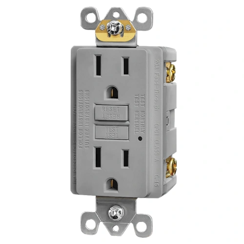
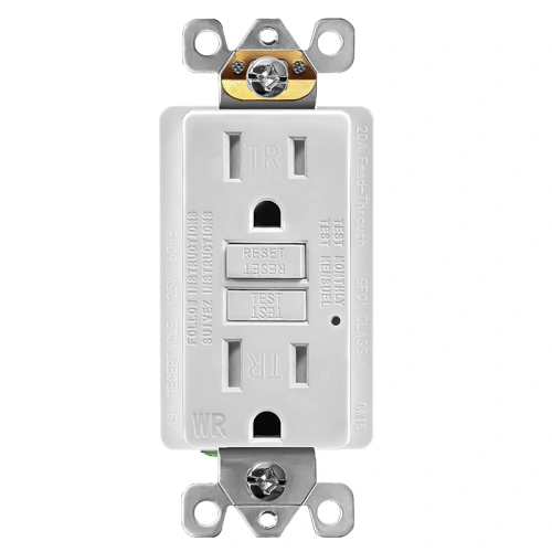
What is a non-tamper-resistant GFCI receptacle?
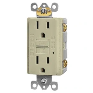
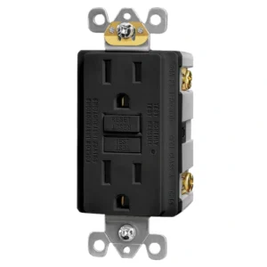
A non-tamper-resistant GFCI receptacle is a ground-fault circuit interrupter outlet without internal shutter mechanisms that block foreign object insertion. It provides the same Class A ground-fault protection as a TR model but is designed for locations where tamper-resistant construction is not required by the applicable electrical code. Non-TR GFCI receptacles are code-compliant for commercial maintenance areas, industrial facilities, and locations not listed under NEC 406.12. Always verify TR requirements with the authority having jurisdiction for your specific installation.
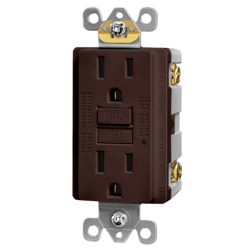
Where is a non-TR GFCI receptacle typically used?
Non-TR GFCI receptacles are typically used in indoor commercial and industrial environments where ground-fault protection is required but tamper-resistant shutters are not mandated by the governing installation standard. Common applications include commercial utility rooms, mechanical spaces, facility maintenance replacements, and industrial control areas. Contractors and MRO buyers also use non-TR models for like-for-like replacement of existing non-TR devices in buildings where NEC 406.12 TR requirements do not apply to that location.
When are tamper-resistant receptacles required by code?
NEC Section 406.12 requires tamper-resistant receptacles in specific occupancy types and locations — including dwelling units, hotel and motel guest rooms, educational facilities, childcare facilities, and certain healthcare and assisted-living spaces. The requirement applies to 15A and 20A, 125V and 250V nonlocking-type receptacles in the covered locations. Installations outside these defined categories may use non-TR receptacles. Always confirm the locally adopted NEC edition and any local amendments before specifying a non-TR device.
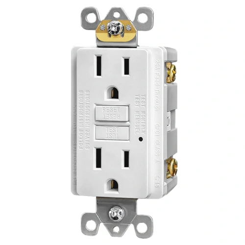
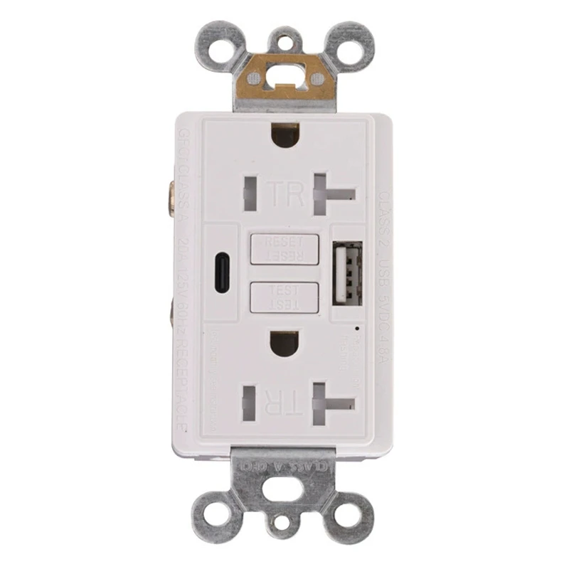
Does this GFCI receptacle include self-testing?
Yes. This receptacle performs automatic periodic self-testing of its internal ground-fault protection circuit, as required by UL 943 for Class A GFCI devices manufactured after the June 2015 amendment. If the self-test detects a protection failure, the device locks out the reset function and disables power to the face, preventing a failed GFCI from being reset and left in service. Refer to the product documentation for specific self-test interval details.
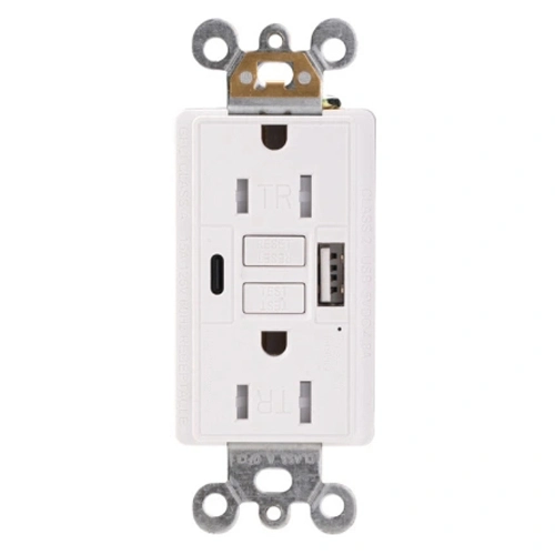
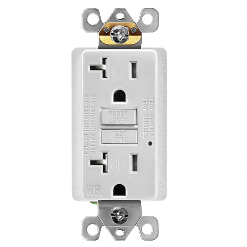
Can a 15A GFCI receptacle be used on a 20A branch circuit?
Yes. NEC 210.21(B)(3) permits a 15A receptacle on a 20A branch circuit when the circuit serves two or more receptacle outlets. This is standard practice in commercial and multi-unit residential installations. The GFCI protection function operates independently of the branch circuit amperage rating. Always confirm the final circuit design with the authority having jurisdiction.
Can this GFCI receptacle be used in damp or wet locations?
No. This is a non-weather-resistant (non-WR) GFCI receptacle designed for dry indoor locations only. Damp or wet locations — such as outdoor areas, garages with direct weather exposure, or unenclosed porches — typically require a WR-rated device installed with a weatherproof cover per NEC 406.9. For those applications, see the 15A TR WR Self-Test GFCI Outlet.
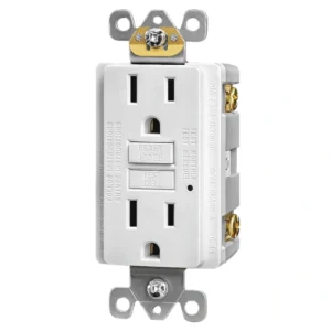
What does the LED indicator mean on this GFCI?
The LED indicator provides visual feedback on the device’s protection status. A steady green light typically indicates the GFCI is powered and protection is active. A red light or flashing indicator signals a protection fault or end-of-life condition, meaning the device should be replaced. Press TEST to confirm proper trip function, then press RESET to restore power. Refer to the product label and installation instructions for model-specific LED behavior.
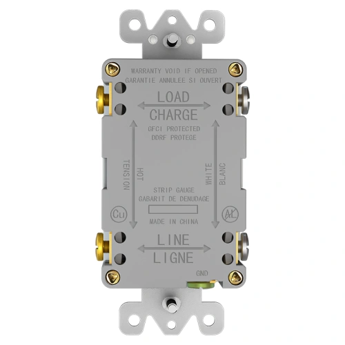
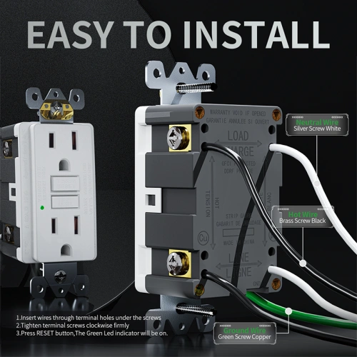
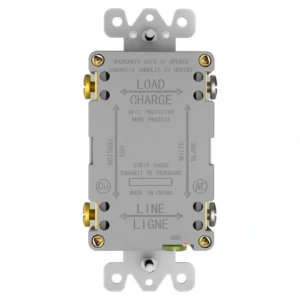
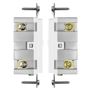
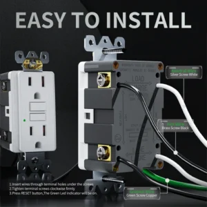
Does this GFCI protect downstream outlets on the LOAD terminals?
Yes. When wired correctly using the LOAD terminals, this GFCI receptacle extends ground-fault protection to downstream receptacles on the same branch circuit. The hot and neutral wires feeding downstream devices connect to the brass and silver LOAD terminals respectively. Do not reverse LINE and LOAD connections — incorrect wiring will prevent the GFCI from providing downstream protection and may trigger a wiring fault indicator.