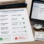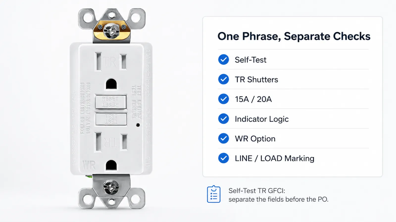
A line on a quote reads “15A Self-Test TR GFCI.” It looks finished. It isn’t a spec yet — it’s three different checks stacked into one phrase, and the phrase hides which ones still need an answer. It tells you the device has ground-fault protection, that the protection monitors itself, and that the face has tamper-resistant shutters. It says nothing about how the device signals end of life, how the LOAD terminals are marked, or whether it’s weather-resistant. On a project that gets maintained by someone who wasn’t there at install, they’re the difference between a clean handover and a string of “is this one bad?” calls.
| Field on the line | What it actually verifies | What it does not settle |
|---|---|---|
| Self-Test | The GFCI monitors its own ability to trip under UL 943 | How the model behaves at end of life — power denial, visual indication, audible indication, or another listed response |
| TR | A listed mechanical shutter on the receptacle face under UL 498 | Nothing about ground-fault protection |
| 15A / 20A | NEMA face and device rating | Whether the SKU is WR for damp or wet locations |
| GFCI | Class A ground-fault protection | Indicator-light logic, terminal style, and project labeling |
Self-test and tamper-resistant get printed side by side so often that they read like two names for “the safer outlet.” They aren’t. They’re two unrelated jobs done by two unrelated parts, listed under two different standards, and a buyer confirms them separately or not at all.
Self-Test Is the GFCI Watching Itself, Not the Shutter
The self-test part lives entirely inside the GFCI. Since 2015, UL 943 has required new GFCIs to monitor their own protective circuitry on a schedule and to respond when that circuitry fails. The standard allows defined failure responses such as power denial or a visual or audible indication. Which path a given model takes is a design field, and it belongs on the datasheet instead of being hidden behind the words “self-test.”
It does not retire the TEST button. Auto-monitoring checks the electronics; it isn’t the manufacturer telling anyone to stop pressing TEST. The two coexist, and the datasheet should make clear which end-of-life behavior the model uses, because that’s the field people get wrong.
The indicator light is where the wrongness usually starts. Red, green, blinking, solid, none — the meaning is set per model, written in that model’s sheet, and there is no standard color code across brands you can lean on. A green light on one line means powered and passing; on another there’s no light at all by design. Treat the indicator as a field to read off the specific sheet, not a fact you carry from the last GFCI you handled. When a unit won’t reset or shows a status nobody can place, whether the GFCI has actually failed is its own diagnosis, separate from anything on the spec.
TR Is a Shutter, and It Is Not Ground-Fault Protection
Tamper-resistance is mechanical. Inside the face is a listed shutter under the receptacle standard that stays closed until both blades push in at once; a single object in one slot meets a blocking face and goes nowhere. It is there to resist single-object insertion into a live slot. It has no bearing on ground faults, and the NEC question of where TR is required is a separate one we keep in our TR and WR selection guide.
The common read is that a TR face is simply harder to plug into — that the shutter is a tax you pay in stiffness. That isn’t the design intent, and it isn’t how we let our parts ship. We verify it directly: after each batch of TR shutter parts, we assemble samples with the shutters but no circuitry, measure on a force gauge how much push a plain non-TR receptacle needs to accept a plug, then push a TR sample with that same force. If the difference lands under five percent, the batch passes, and we check around two percent of the run — same parts, same material, same parameters across a batch, so a sample stands in for the lot.
So “the plug won’t go in” doesn’t point at the GFCI, and it isn’t something to file as normal TR behavior to live with. Check the plug first — a bent blade, a worn blade, or a plug going in crooked. A plug that’s straight and sound and still fights the slot is a single-device signal, not a property of TR. The blade-retention side of that, and what we check in production, sits in our plug retention test write-up.
Two Complaints, Two Different Diagnoses
The reason to keep these apart isn’t academic. The two things that come back from the field split cleanly, and trying to read them with one rule wastes a trip.
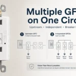
A dead outlet, a red status, a unit that won’t reset — that’s the GFCI side. Look at the self-test state, the wiring, the LINE/LOAD landing, and whether the device has reached end of life. A plug that won’t seat is the other side entirely, and it routes to the plug and the shutter, not to anything the GFCI does. One return judgment can’t cover both, and a line that only said “Self-Test TR GFCI” gave whoever’s holding the complaint no way to tell which bucket they’re in.
COMPLAINT FROM THE FIELD
│
├── Dead outlet / red light / won't reset ──▶ GFCI side
│   Check: self-test state · wiring · LINE/LOAD · end-of-life response
│
└── Plug won't seat ───────────────────────▶ Plug + shutter side
    Check: plug blade · insertion angle · single-device shutter fault
    Not: a GFCI fault
    Not: "normal TR stiffness"
What the Line Should Actually Carry
If you’re writing the PO or the spec, the fix is to un-stack the phrase. The device with the buttons is the GFCI; tamper-resistance is a separate listing on the same body; the rest are their own lines:
- 15A or 20A, with the NEMA face called out.
- UL/cUL listed — GFCI to UL 943, the receptacle and its TR shutter to UL 498.
- Self-test, with the end-of-life behavior named: power denial, indication, or the listed response shown on the model sheet.
- Reset lockout stated, not assumed.
- Indicator logic taken from the model sheet, not a generic “LED.”
- TR marked on the device; WR added only where the location is damp or wet.
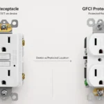
- LINE/LOAD marking and terminal type, so the downstream protection is documented at the outlet.
- Un-stacking this phrase is the move every GFCI line needs; the datasheet is just where it bites hardest. The rest of what a finished-looking GFCI line still leaves open is in what a clean-looking GFCI order still has to settle.
What We Control, and What We Don’t
We can speak to the device and the carton. Our GFCIs come as self-test models, in non-TR, TR, and TR/WR, in 15A and 20A, with LINE and LOAD marked on the body, the LOAD terminals covered until protection is deliberately extended, an instruction sheet that lays out the feed-through wiring, and “GFCI Protected” labels in the box. The TR sampling above is ours to run, and we run it on every shutter batch.
What we can’t do from here is read your building. We don’t install the device, we don’t decide which indicator light your maintenance team will be looking at across a mixed inventory of brands, and we don’t make the AHJ’s call on where TR is required. Those stay on the site. What we can hand you is a device whose datasheet says all of the things the short phrase left out.
Frequently Asked Questions
What is a self-test GFCI receptacle?
A self-test GFCI receptacle monitors its own protective circuitry on a schedule and responds when that circuitry fails. The self-test is about the GFCI’s own health, not about the shutters or the plug fit.
Does a self-test GFCI still need manual testing?
Yes. Auto-monitoring checks the electronics; it does not replace the TEST button. The model sheet should say how often it self-tests and what it does when a check fails.
Is a tamper-resistant GFCI the same as a self-test GFCI?
No. Tamper-resistance is a mechanical shutter on the face. Self-test is the GFCI checking its own protection — and under current UL 943 that auto-monitoring is part of how a Class A GFCI is built, not an add-on feature you opt into. What still varies, and what you verify, is how a given model handles a failed check and how it signals it.
Does tamper-resistant mean GFCI protected?
No. TR blocks foreign objects from a single slot. GFCI protection senses a ground-fault imbalance and cuts power. Different parts, different standards, different risks.
Why is my tamper-resistant outlet hard to plug into?
Start with the plug. Bent blades, worn blades, and crooked insertion can all make a TR shutter feel blocked. If a sound plug still will not seat when inserted straight and evenly, treat that as a possible single-device defect rather than normal TR behavior.
What does the indicator light mean on a self-test GFCI?
It depends on the model, and only the model. There is no color code shared across brands. Read it from that device’s sheet rather than from the last GFCI you used.
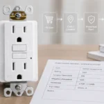
What should buyers compare on a self-test TR GFCI datasheet?
The fields the short phrase skips: end-of-life behavior, reset lockout, indicator logic, terminal type, LINE/LOAD marking, NEMA face and amperage, and WR where the location calls for it.
How This Fits With the Rest of What We’ve Written
This piece is about one phrase carrying more checks than it admits, so it stays out of the territory the others own. Where TR is required, and how WR factors into damp and wet locations, is the job of our TR and WR selection guide. Whether a GFCI that won’t reset has actually failed belongs to our piece on whether GFCIs go bad. The plug-fit and retention side, and what we check on the line, is in the plug retention test write-up. Read together, they keep the device, the shutter, the protection, and the marking as four separate things rather than one bundled feature.
Sources
- UL 943, Standard for Safety for Ground-Fault Circuit Interrupters — Class A GFCI scope for personnel protection:
UL 943 Standard page - IAEI Magazine, UL Question Corner: Self-testing GFCI Requirements — UL 943 auto-monitoring and self-test requirements for GFCIs:
Self-testing GFCI requirements - ESFI, Tamper-Resistant Receptacles White Paper — TR shutters and single-slot foreign-object protection:
Tamper-Resistant Receptacles White Paper
Specifying self-test TR GFCIs for a project?
If you want a datasheet that actually names the end-of-life behavior, indicator logic, terminal type, and TR/WR variant — instead of one stacked phrase — see our GFCI receptacle category, or send the line items and we’ll fill in the fields the short version leaves blank.