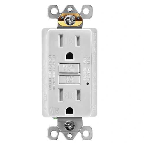
What is a 20A weather-resistant self-test GFCI receptacle?
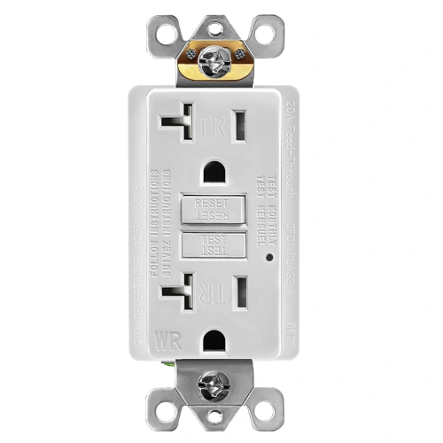
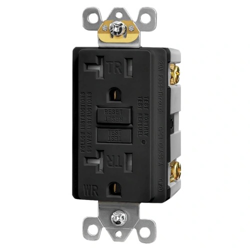
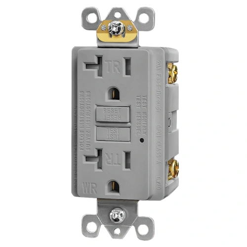
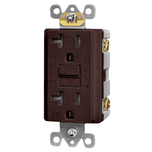
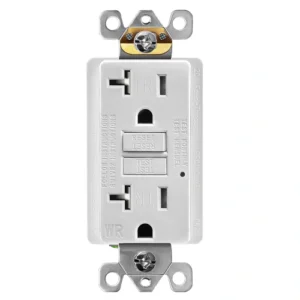
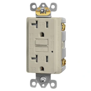
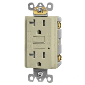
A 20A weather-resistant self-test GFCI receptacle is a NEMA 5-20R wall device that combines Class A ground-fault protection, weather-resistant construction, tamper-resistant shutters, and automatic self-test monitoring in one 20A receptacle. It is used when a project needs a higher-capacity outdoor or moisture-exposed GFCI rather than a standard indoor 15A or non-WR device.
Does a WR GFCI still need an extra-duty in-use cover in wet locations?
Yes. NEC 406.9(B)(1) requires 15A and 20A, 125V and 250V receptacles in wet locations to be weatherproof whether or not a plug is inserted, and the outlet box hood for that purpose must be listed and identified as extra-duty. A WR receptacle improves the device’s durability, but it does not replace the required cover in wet locations.
Are tamper-resistant shutters still required for some outdoor locations?
Yes. NEC 406.12 requires tamper-resistant receptacles for specified 15A and 20A, 125V and 250V nonlocking receptacles in covered locations. When the outdoor installation falls within those covered occupancies or access conditions, a WR receptacle alone is not enough, and a TR feature is still required.
Can this 20A WR GFCI be used on a 15A branch circuit?
No. This is a 20A NEMA 5-20R receptacle, so it should not be used as a standard 15A replacement. For buyer-facing selection, the safe rule is to use a 20A receptacle on a 20A branch circuit and confirm the final installation against the circuit design and adopted code.
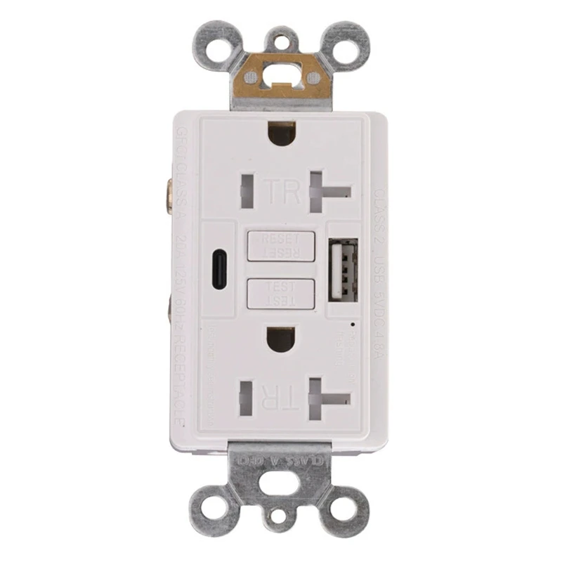
Will a standard 15A plug fit into this 20A NEMA 5-20R GFCI?
Yes. A NEMA 5-20R receptacle is designed around the 20A T-slot face pattern, and that format accepts standard 15A straight-blade plug use as well as 20A plug configurations. On a tamper-resistant model, the shutters open when the plug blades apply even pressure during normal insertion.
Does this model include self-testing?
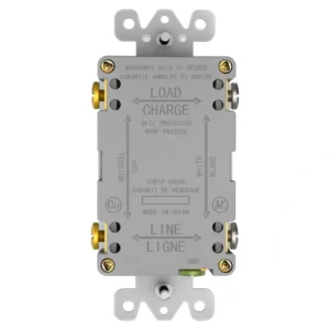
Yes. This receptacle is built as a self-test GFCI, and UL 943 applies to Class A GFCIs intended for personnel protection. That makes it suitable for buyers who want a current self-test 20A WR/TR GFCI instead of an older non-self-test replacement.
Can this receptacle be used outdoors in damp or wet locations?
Yes. This is a weather-resistant GFCI receptacle designed for outdoor, damp, or wet-location applications when it is installed with the required listed weatherproof cover and in accordance with the applicable code and installation conditions. WR construction supports the outdoor rating, but the full installation must still match the enclosure and cover requirements for the location.
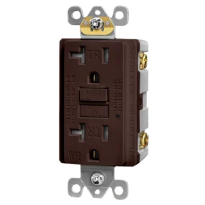
What does weather-resistant mean on a GFCI receptacle?
Weather-resistant means the receptacle is built for tougher exposure conditions than a standard indoor device. In your WTST20 brief, WR is tied to exterior-use durability language such as resistance to ultraviolet exposure and corrosion, which is why a WR GFCI is the correct starting point for outdoor and moisture-exposed receptacle selection.