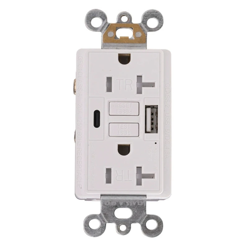
What is a 20A self-test GFCI outlet?
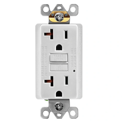
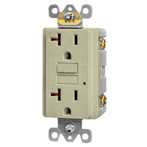
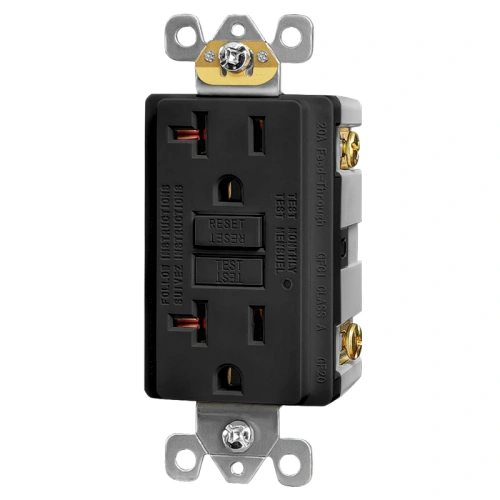
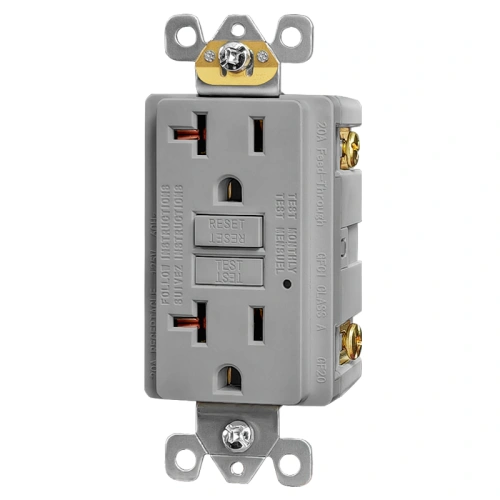
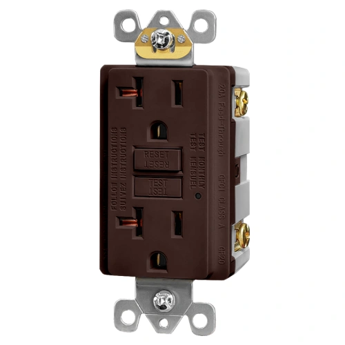
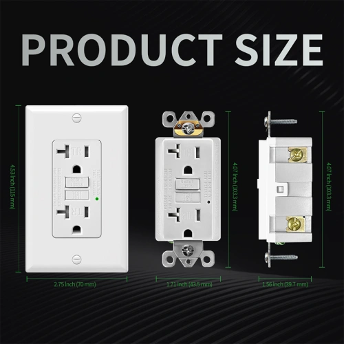
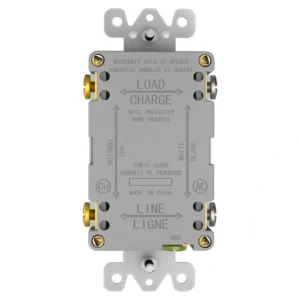
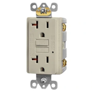
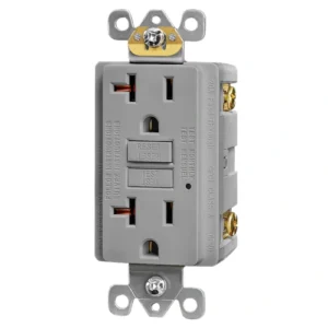
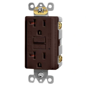
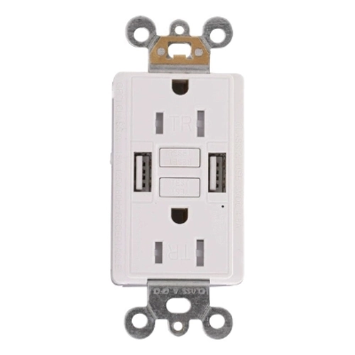
A 20A self-test GFCI outlet is a ground-fault receptacle built in a 20 amp device format with automatic self-test monitoring. On this model, that includes a 125V rating, a NEMA 5-20R face, and Class A GFCI protection. It is the right choice when the project calls for a 20A wall receptacle format rather than a standard 15A face.
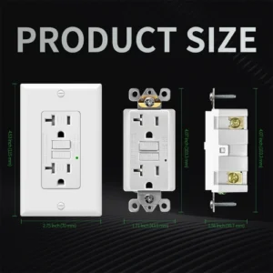
How can I identify a 20A GFCI receptacle?
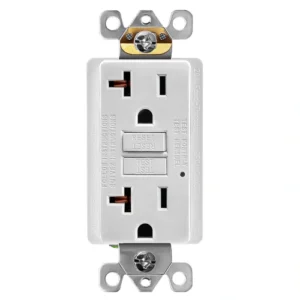
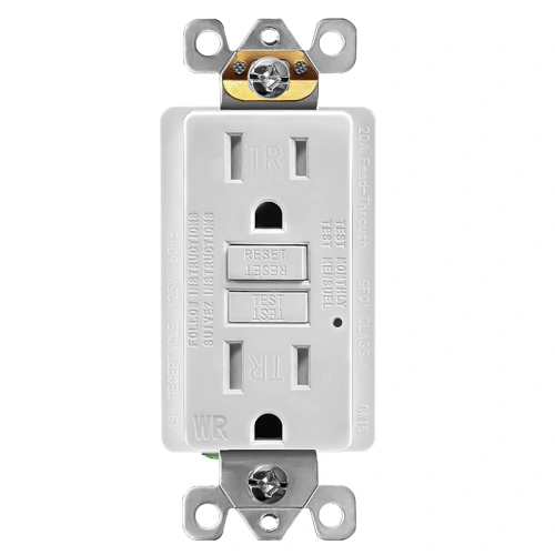
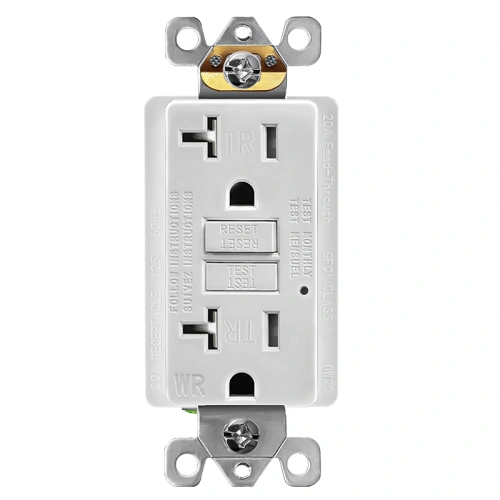
The easiest way is to look at the receptacle face. A 20A GFCI uses a NEMA 5-20R configuration, which includes the T-slot pattern that distinguishes it from a standard 15A face. This ShengYu model is also listed as a 20A, 125V, self-test GFCI receptacle on the live specification section.
Does this model include self-testing?
Yes. This is a self-test GFCI outlet, and the current product page identifies it as a self-test GFCI within the UL 943 certification framework. That makes it suitable for buyers looking for a current-generation GFCI replacement rather than an older non-self-test format.
Is this a tamper-resistant 20A GFCI?
No. This page clearly identifies the receptacle as non-tamper-resistant. Buyers should choose this model only for locations where a non-TR device is appropriate for the project scope. If the installation falls within NEC 406.12 tamper-resistant locations, the correct selection is a TR GFCI rather than this non-TR version.
Is this outlet weather-resistant?
No. This product is listed on the page as non-weather-resistant, so it should be positioned as an indoor GFCI receptacle. If the project needs a device for damp or wet locations, use a WR-rated GFCI instead of this model.
What does the T-slot mean on a 20A GFCI outlet?
The T-slot is the face pattern used on a NEMA 5-20R receptacle. It is the visual identifier that tells buyers they are looking at a 20A receptacle format instead of a standard 15A face. For project sourcing, this matters because the receptacle configuration should match the device format required by the job.
Where is a non-TR 20A GFCI outlet typically used?
This type of 20A GFCI is typically used in indoor commercial replacement, equipment-support, maintenance, and other project environments where a 20A GFCI format is required and the installation does not call for a tamper-resistant device. It is better suited to code-aware product selection than broad residential-style positioning.
What NEC issue should buyers check before specifying a non-TR 20A GFCI?
The key NEC issue is whether the installation location falls within the tamper-resistant receptacle requirements of Section 406.12. Public NEC materials continue to show that 15A and 20A, 125V and 250V nonlocking receptacles in specific locations must be tamper-resistant. If the jobsite falls within that code scope, use a TR GFCI instead of this non-TR model.